|
|
Contest logging software for winning CW, SSB, RTTY, and PSK31.
|
|
|
|
W5XD Multi-function Keyer As of July, 2001, this keyer is offered only as a close-out. When we sell out of our available stock, there will be no more kits available. Please look at our pre-assembled version instead.
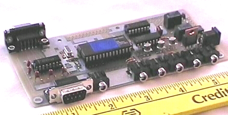
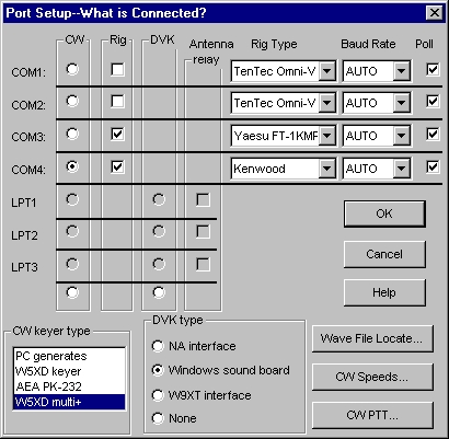
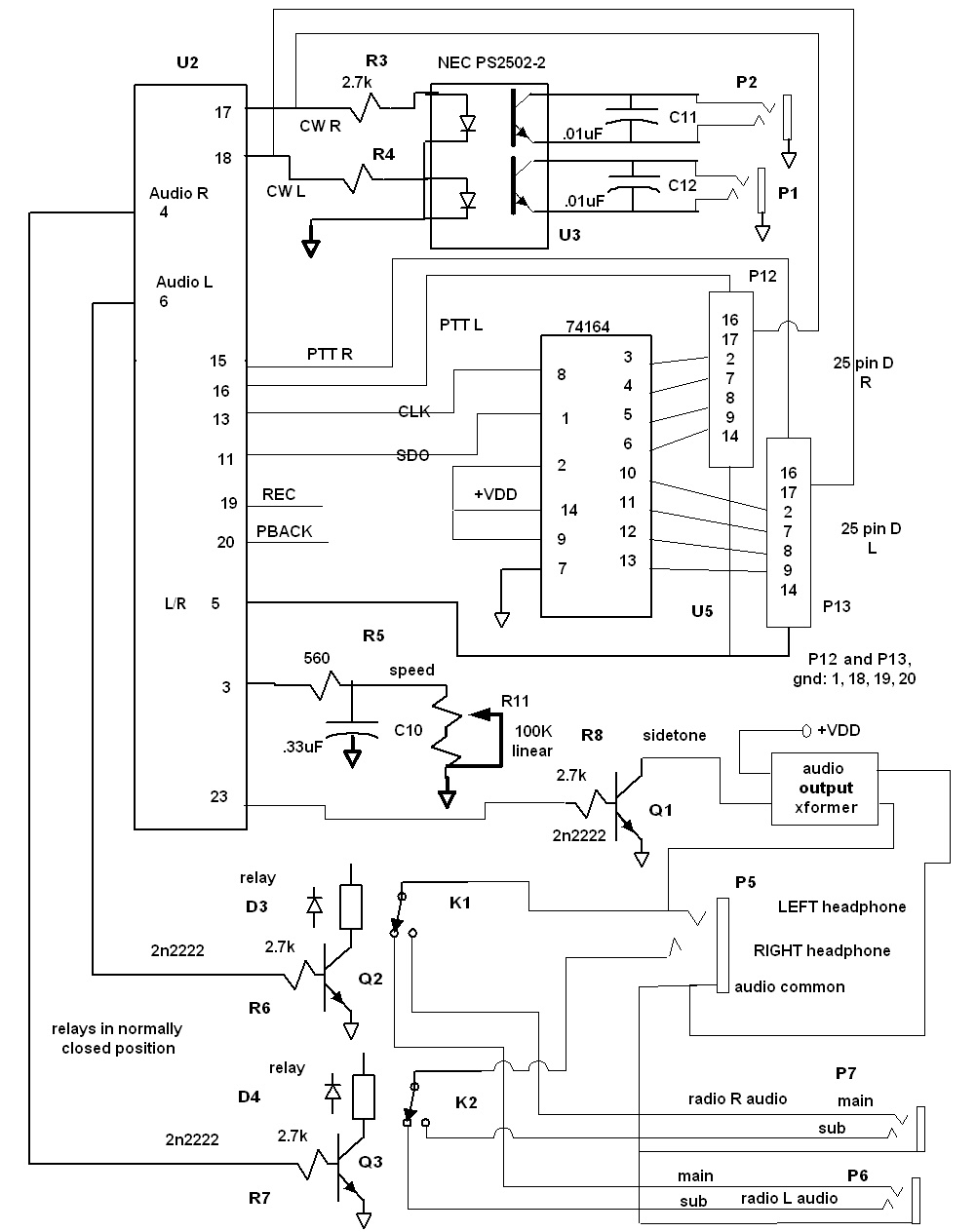
The W5XD multi-function keyer is a device that connects to your PC via a serial port and provides a variety of functions needed for a contest operation that WriteLog provides no other way. All functions work on Windows 95, 98, Windows NT, and Windows 2000. The multi-function keyer provides these functions in a "cafeteria plan". You may chose to use any or all of the functions without using others. The functions it provides are: 1. CW generation independent of the processor load on your PC running WriteLog. The "PC generates" CW option in WriteLog is vulnerable to timing disruptions caused by multi-tasking on your PC. If you run only WriteLog during your contesting operations, you probably won't hear any CW timing problems, but some network drivers, CD writers, etc. have been known to multi-task poorly enough to affect WriteLog's CW generation. 2. Separate opto-isolated CW outputs for a Left and a Right rig. WriteLog's PC-generates CW function provides a single CW output plus a L/R output signal which requires an external relay to route separately to Left and Right rigs. 3. As an alternative to (2), the multi-function keyer provides separate TTL-level CW outputs on pin 17 of each of two LPT port connections if you already have LPT-to-CW cables compatible with other logging program CW outputs. 4. Paddle inputs for sending CW. Touching a paddle aborts any PC-generated CW in progress. WriteLog provides an INI file option to select your preference of the "automatic letter space" keyer mode. With the auto spacing turned ON, the paddle-sent CW extends any space between symbols that's longer than a dot space to the 3 dot space inter-letter morse standard. 5. Antenna relay outputs separately for Left and Right rigs. The same pin out WriteLog supports on standard LPT ports for antenna relays is supported on the multi-function keyer. 6. Headphone audio switching. The audio relays in the multi-function keyer are controlled by WriteLog to match the 2 radio Entry Window in WriteLog according to the settings you have made in WriteLog's Radio menu entries. The menu entries include both headphones connected to the active radio or one headphone to each radio. In either mode, there is a headphone latch menu entry that causes WriteLog to latch both headphones to the inactive radio until the transmission in progress finishes. When the transmission finishes, the headphones return to their previous setting (both ears on the active radio, or one ear on each radio). 7. The Antenna relay, PTT, and CW outputs on the multi-function keyer LPT port outputs work on all current Windows operating systems: Windows 95/98/NT/2000. This keyer is the only method for supporting antenna relay outputs from WriteLog on Windows NT and Windows 2000. Because of parallel port driver limitations, WriteLog does not support the LPT ports on Windows NT/2000 PCs. 8. The multi-function keyer requires an RS-232 connection to your PC, but it can support all the above functions and rig control for one rig on just one serial port. Assuming you already were doing rig control on a serial port, then the multi-function keyer requires no additional ports on your PC. 9. The multi-function keyer generates a CW sidetone in the Left headphone for both Left/Right CW transmissions. Or, you may wire the audio output to a speaker instead. The CwSidetonePaddlesOnly in Writelog.ini tells WL to not generate a CW sidetone for PC-generated CW. 10. The keyer supports connecting a speed control potentiometer and a SPST switch to control CW speed and left/right radio switching manually without the PC running. Availability The circuit board described here and the required MC68HC705P9 microprocessor chip are available now direct from K5DJ. Prebuilt boards or enclosures are not available. The photograph above is of a prototype version of the board before installation of the 25 pin LPT port jacks. Production versions of the board have silk screen labeling of all parts and connectors. Connections There are three connections you must make to the multi-function keyer, and there is one function you must use in order to use any of the other functions: 1. Power. The keyer requires between 7.5V and 25V DC at P9 in either polarity. 2. You must connect RS-232 to the PC on the 9 pin D connector at P11. Use WriteLog's Setup Port... menu to indicate which COM port you are using on your PC. Version 10.10 of WriteLog is required. In the same menu, select the W5XD multi+ keyer to the lower left.
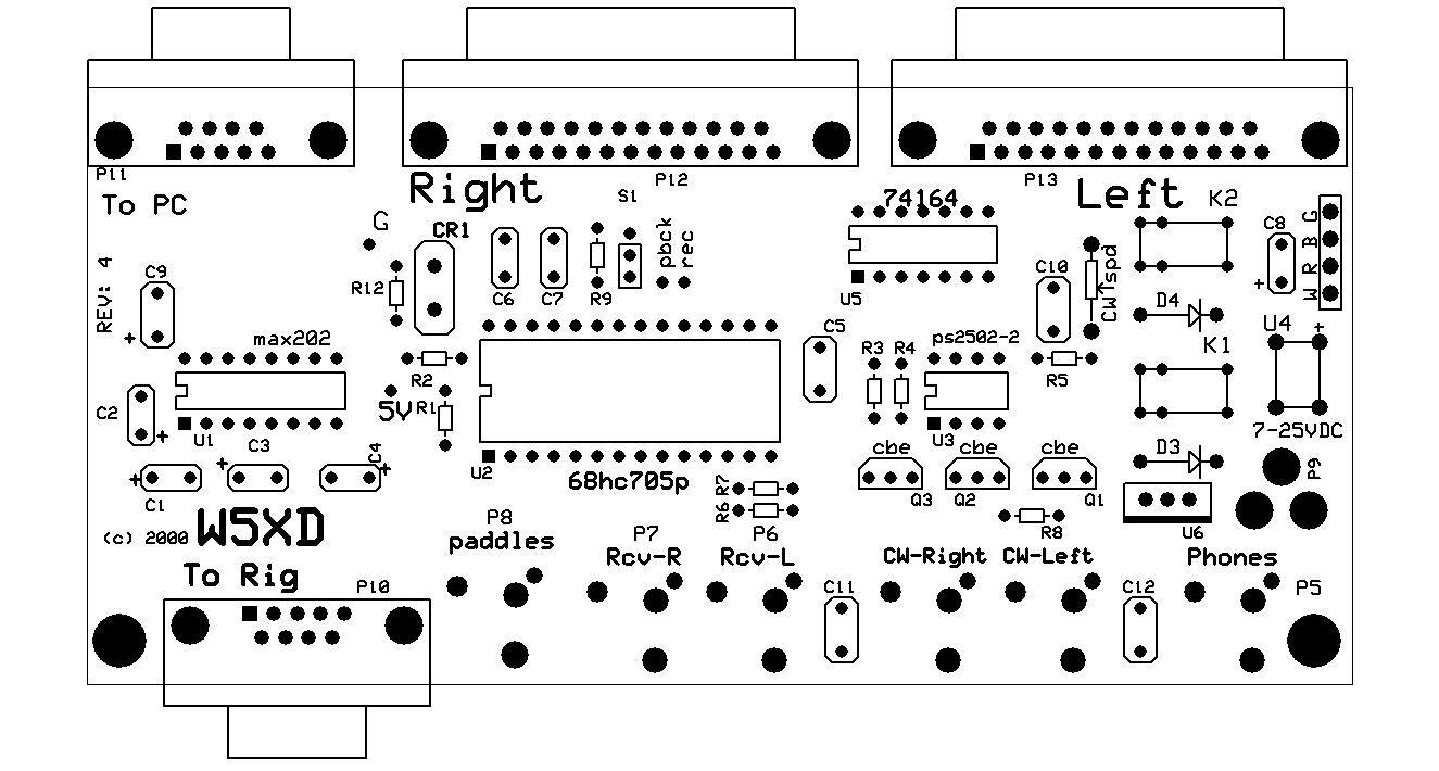
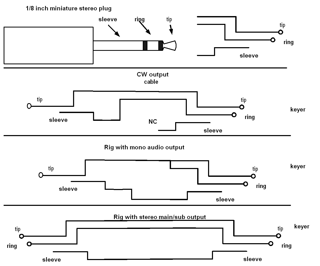
3. You must use the multi function keyer to generate CW to enable the keyer's other features. This means you must connect P1/P2 to your rig's CW input CW (or, alternatively) the TTL levels on pins 17 of P12/P13 to a standard contest keyer cable to your rig. 4. You may connect CW paddles to P8 5. You may connect receiver audio to P6 and P7, which the keyer will route to P5 for your headphones 6. You may connect a rig's PC control port to P10. This way, a single COM port supports both PC control of a rig and control of the multi-function keyer. 7. You may connect to the antenna relay, PTT, and/or CW outputs on P12 (for the Left rig) /P13 (for Right). Note, the Top Ten Devices antenna relay requires a ground connection on pin 25 of P12 and P13 that is not on the circuit board we sell. Please see the Keyer Board Modification page for documentation on adding the necessary jumper wire. 8. You may connect an audio output transformer, Radio Shack number 273-1380, to the circuit board pads labeled WRBG to enable the keyer's side tone generator. The white/red pair from the transformer can be connected to a small speaker instead of the circuit board so the side tone will be heard on the speaker instead of the headphone. 9. You may connect an SPST switch to the PCB connection labeled S1 (or mount a switch on the board itself). The switch will control the left/right radio selection without WriteLog running. 10. You may connect a 100K ohm linear potentiometer to the PCB connection labeled "CW spd". The pot will control the CW speed. Connector placement
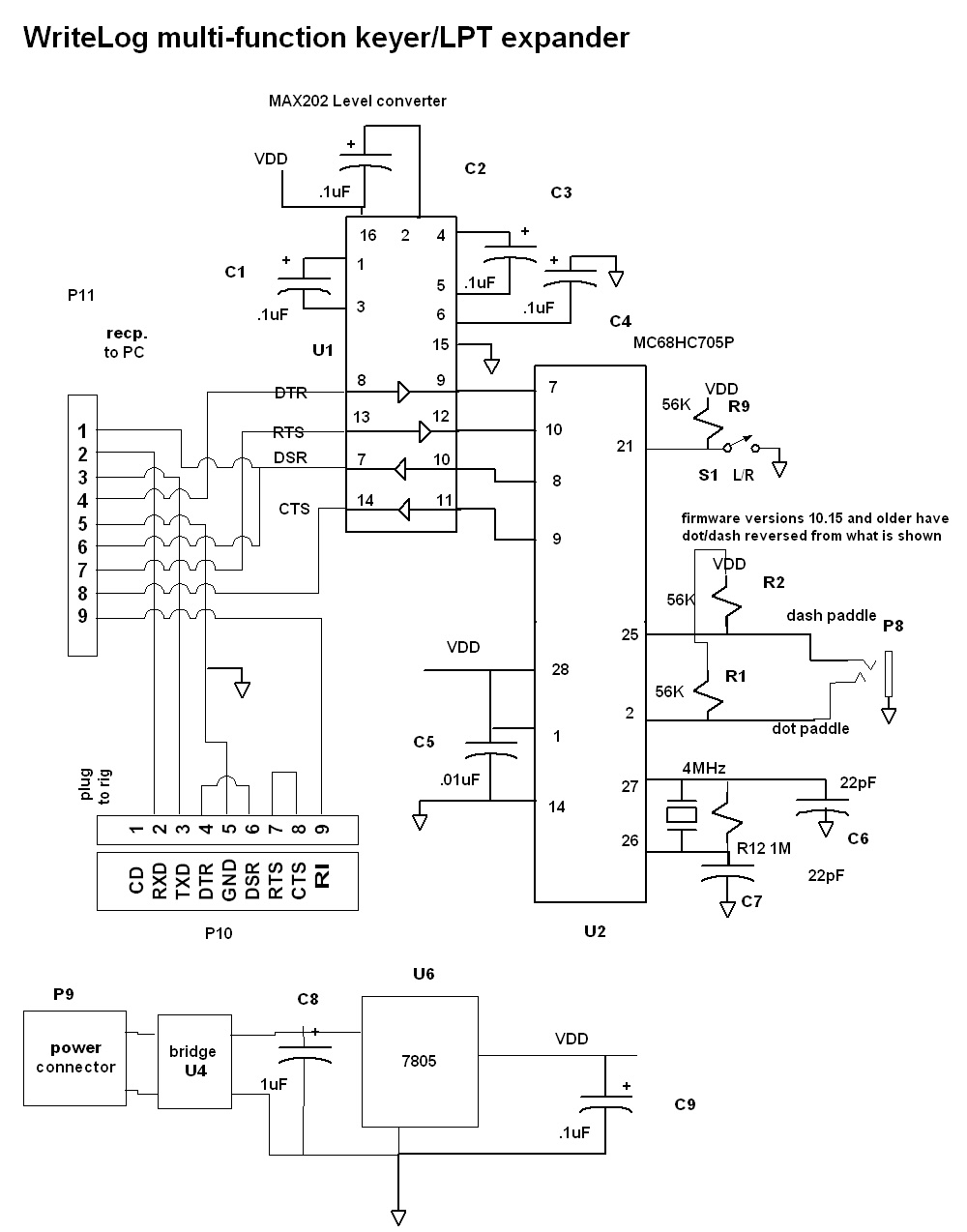
Circuit Diagram (page 1) (page 2)Construction note The three transistors on the keyer board, Q1, Q2, and Q3, are labeled with a text "cbe" and with a package outline with a flat side. The flat side of the package outline on the board silkscreen is wrong! The "cbe" labels correctly indicate how to install the transistors. Firmware Revisions Version 10.74
Version 10.26
Version 10.19
version 10.15 Example Software Here is a zip file, KeyerDemo.zip, containing some software routines in C++ that drive this keyer using the Win32 API.
|
|